Current transformers
A current transformers is also referred to as a CT. Low voltage Current transformers can be divided in instrument- and protection current transformers.
Instrument current transformers
Instrument transformers, class 0,1 up to and including class 5, comply with the rate of accuracy as stated in the table below, up to 120% of the rated current. Current transformers can be loaded up to the rated current continuously.
Current error and phase displacement as function of the rated current
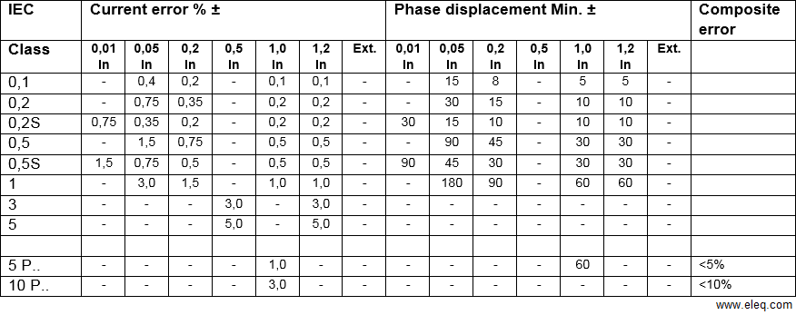
IIn the special ‘extended’ design of an instrument current transformer it will be possible to extend the continuous overload current and accuracy considerably.
Example: 300/5A, class 1 extended 300%
An instrument current transformer retains its accuracy up to 300% of the rated current (in this example up to 900A) and can also be overloaded up to that value. The rate of overload is stated in % directly after the accuracy class designation ext….
The special 0,2S and 0,5S class transformers are used in cases where measurements in the lower current range (0,01 to 0,2 In) must meet extra requirements in terms of accuracy.
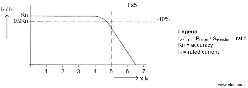
ELEQ instrument current transformers are supplied with instrument security factor Fs5 at 50Hz, unless otherwise specified. With stock supply transformers the instrument security factor applies both at 50 and 60Hz.
Fs5 implies that, at 5 times In, the composite error of the transformer due to saturation of the core is at least 10%. This applies if the transformer is loaded with the rated burden specified on the rating plate. At lower loads the instrument security factor increase, reducing the protective action to the transformer.
Transformers for electronical purpose
These Low voltage current transformer are destined to control electronic circuits. For this purpose a voltage proportional to the primary current is generated at the secondary terminals. In standard design the rated voltage on the secondary terminals will be 2 Volts. Other voltages on request.
To adjust the secondary voltage of such a transformer to the need of a specific electronic circuit a voltage divider, may be used. The proportional accuracy between the primary current and the secondary voltage will remain.
Auxiliary current transformers
To transform a secondary current from 5A to 1A or even lower. With these it is possible to bridge a longer distance as would be possible with a secondary current of 5A. A measuring lead of 100 meters (double leads) has a power consumption of 35VA at 5A.
This will only be 1,4VA for a secondary current of 1A. However, the extra load of the auxiliary current transformer (2-4VA) must be considered.
An auxiliary current transformer can also be used to raise the secondary current of a main current transformer in order to obtain a more accurate reading on the instrument. Generally therefor, there won’t be left enough output for the connected instruments.
For example: A main current transformer of 800/5A with a rated output of 25VA will supply at 400A not more than 6,25VA. And from this must be substracted the power consumption of the auxiliary current transformer (2-4VA).
Load resistors for current transformers
The measuring accuracy of a current transformer is related to the connected burden. The standardization requirements laid down in IEC state that the accuracy class is based on a connected load ranging from 25 to 100% of the rated burden indicated on the rating plate.
The point in question must be taken into account when connecting measuring equipment, and particularly when replacing such equipment in existing installations. The considerably reduced internal consumption characterizing some of today’s measuring and switch gear may cause the overall connected load to be less than the requisite minimum of 25%. The same applies to the instrument security factor FS.., which is based exclusively on the rated burden. At lower loads, the instrument security factor increases, resulting in partial loss of the transformer’s protective action.
Application of ELEQ’s reactance-free load resistors, which can be incorporated into the secondary current circuit, permits adaption of the total circuit load to the minimum requirement.
Summation current transformers
For electrical summation of current of synchrone power supply systems, in different groups of the same phase.
In case of using the summation current transformer with several main current transformers, with different ratios, these main ratios must be stated in the order.
When calculating the rated output of a summation current transformer, the available output of all main current transformers and the own power consumption of the summation current transformer must be taken into account.
For main current transformers with different ratios, the necessary output for each main current transformer will be proportional to the rated primary current in relation to the total sum of the primary currents.
Example I
The necessary output (Ph) per main current transformer with same ratios is to be calculated by the formula:
Ph = (Ps + Pvs) / N
in which:
Ph = the necessary output for each main current transformer.
Ps = rated output of the summation current transformer.
N = number of main current transformers.
Pvs = power consumption of the summation current transformer.
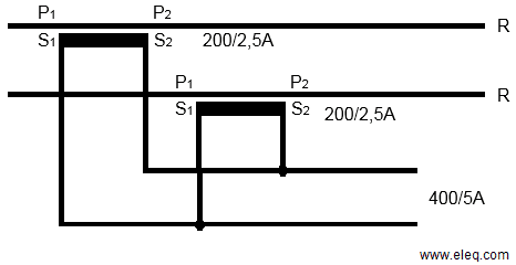
For a summation current transformer of:
(5+5+5) / 5 A, kl. 3, 15VA
With a power consumption (Pvs) of 6VA, the necessary output must be (15+6)/3 = 7VA for each main current transformer.
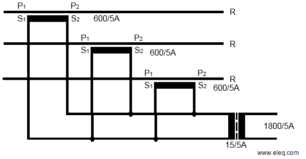
Example II
The necessary output (Ph) per main current transformer with different ratios, is calculated by the formula:
Ph = (I1 + (Ps + Pvs)) / It
in which:
I1 = rated primary current of the main current transformer
It = sum of the rated primary current of all main current transformers
For a summation current transformer of:
((800)5 + (400)5 + (200)5 + (100)5) / 5A, 30VA Kl.1, Pvs = 7,5VA
the necessary output for each main current transformer, will be:
800/5A: (800 x (30+7,5)) / 1500 = 20 VA
400/5A: (400 x (30+7,5)) / 1500 = 10 VA
200/5A: (200 x (30+7,5)) / 1500 = 5VA
100/5A: (100 x (30+7,5)) / 1500 = 2,5VA
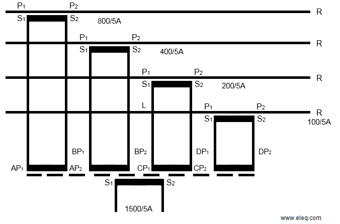
Unused primary terminals of a summation CT remain open.

 +31 (0)521 533 333


 EN
EN  NL
NL